Shock Absorbers
Hydraulic Shock Absorbers
Global business circumstances needs bigger production capacity with high speed. On the contrary, by industrial acceleration impact mass is become heavy and vibration makes tough working conditions, and fatigue energy accumulated on the production facilities. Without proper machines can be damaged easily.
KOBA supplies exceptionally enhanced various products by developing innovative Shock Absorbers by continuous R & D. And also KOBA developed products are optimized general industrial areas which are suffered by shock and vibration. Sophisticated KOBA Products’ life cycle has been prolonged by enhanced durability, the range of effective mass is widened, and the energy absorption capacity is doubled when it comparing with previous model.
You can compare with other impact absorption products like Shock Absorber are Rubber, Spring, and Hydraulic / Pneumatic Devices.
Shock absorption features are as below.
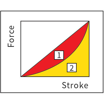
| Rubber & Spring | When decelerating moving object by rubber or spring, the compressed force is not constant and the resistance force is increased gradually, due to that characteristics, impact energy is not absorbed and rather stored, and it transfers impact energy with less absorption to the object. | 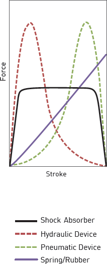 |
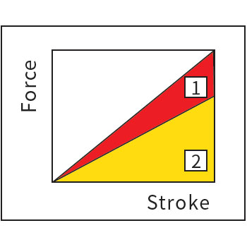
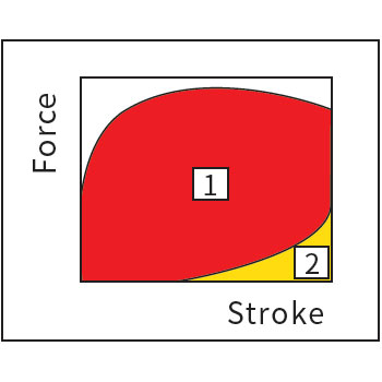
| Hydraulic & Pneumatics Devices | At deceleration moment, single orifice devices like hydraulic cylinder, dashpot, deceleration valve, etc produce big resistance force in initial stage. Rather if pneumatic device is used, gradually the resistance force is increased and maximum the force become biggest at the end of stroke. | |
| KOBA Shock Absorber | KOBA Shock Absorbers absorb impact energy at constant resistance through all the stroke sections by using multiple orifices to minimize the impact force when moving object is stopped. Thus, KOBA shock absorber can stop moving object softly by minimized impact force. |
Shock Absorber’s Overview Structure and Function
- Shock Absorber consists of body, bumper head, piston rod, adjustment dial, and lock nut.
- Thanks to full threaded body it is easy to be installed and precise location fixing is possible. And surface area is increased to dissipate thermal energy fast to atmosphere.
- Bumper head has a role of stopper.
- Piston rod transfers the Impact energy of bumper head to piston.
- Adjustment dial is useful that damping force can be adjusted to impact weight and velocity according to damping conditions.
- Lock nut is useful for installing and fixing shock absorber tightly with body tread installation.
Shock Absorber’s Inner view Structure and Working principle
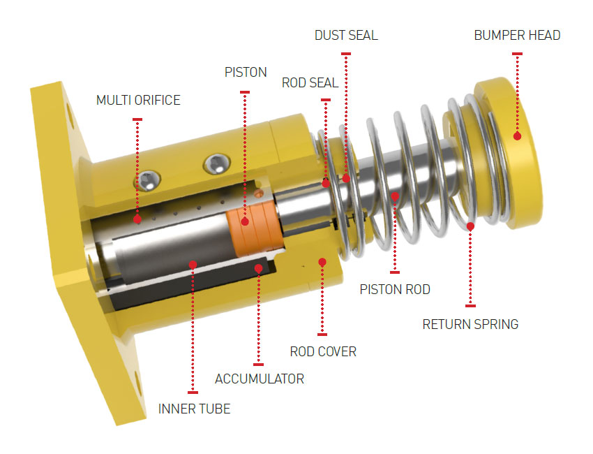
Inside of shock absorber consists of piston, check valve, accumulator, Inner tube, multiple orifice, return spring, oil, etc.
On impacting, the piston rod is inserted into Inner tube and check valve is closed. And it forces oil in the chamber to flow through orifices. At the same time, damping force is generated into piston. Compressed oil which flowed into accumulator is compensating same volume of piston inside. Return process is made by return spring and check valve is opened then piston rod is returned to its original position.
Principal of Energy Absorption
After impacting, compressed oil by piston is to be forced out of Inner tube through orifices. The impact energy is changed into thermal energy then dissipated to atmosphere through threaded body.
Orifice Feature
Single Orifice
Single Orifice Type has a dashpot structure with gap between piston and Inner tube or one hole.
resistance characteristic is shown as below. Orifice area is same on entire stroke section, so resistance force is increased immediately after collision. And as stroke progress, the speed decreases and resistance force minimized at the end.
Multiple Orifices
-
Adjustable
By using multiple orifices, total oil route dimension is decreasing when the stroke is on-going. It enables to maintain total shock absorption safely and softly. Adjustment dial can provide best deceleration features against various collision cases.
-
Self compensating
Operation principal is same of adjustable type. When it set to the optimized orifices’ area is applied, adjustment is not possible after that. Diagram A1 shows high velocity – light impact mass, B1 shows low velocity-heavy impact mass.
Hydraulic Buffer
Operation Principle KHG Series
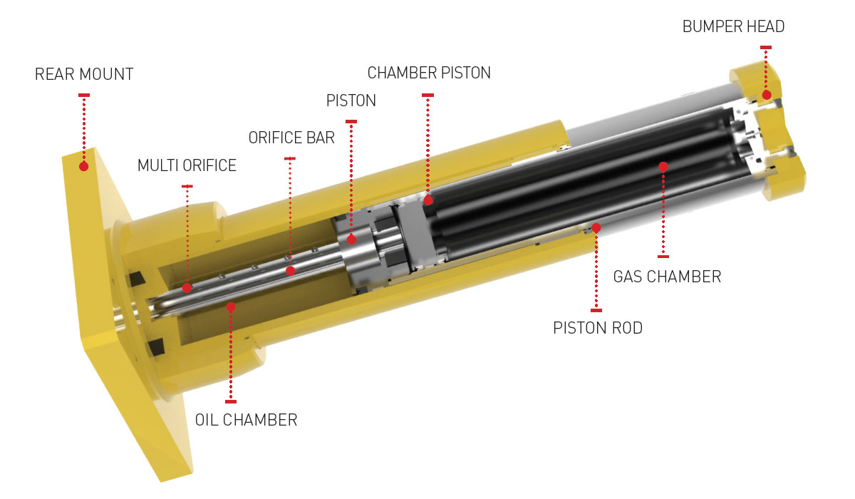
When the moving object collides with the bumper head, the internal check valve is closed and the oil chamber is compressed. The compressed oil flows into the orifice bar through the multiple orifice hole and it absorbs the shock. In addition, as the piston rod enters the inside of oil chamber, the oil amount as much as the piston rod volume presses the chamber piston to compress thd gas chamber(performs the accumlator fumction), so that the pressure inside the gas chamber is increased, absorbs shock energy over the entire stroke ranges.
When the shock absorption is completed, the compressed gas chamber is forced to the oil chamber area, and the check valve installed in the piston is opened to return the piston rod to its original position.
Technical Information
| Model | KHG | KHS |
| Adjustment type | Self adjustment type | Self adjustment type |
| Applied fluid | Oil, N2 Gas | Oil |
| Allowed Speed | 0.2~4.5m/sec | 0.2~3m/sec |
| Temperature ranges | -20~80℃ | -20~80℃ |
| Return mediator | Nitrogen gas | Coil Spring |
| Pistion rod | Hard Chrome (25㎛ or more) | Hard Chrome (25㎛ or more) |
| Body, Bumper head | Epoxy paint coatings | Epoxy paint coatings |
| Application | Over head crane, Transfer car, Stacker crane, Gantry crane, Transport equipment | |
Rubber Damping
- Low dampping
- High spring
Spring Damping
- Low dampping
- High spring
Hydraulic Buffer
- Maximum damping
- Low gas spring
Operation Principle KHS Series
When the moving load is collided to bumper head, the piston rod enters inner tube according to stroke and check valve is closed with the oil chamber compressed.
The oil in chamber is absorbed the impact force by discharging through multiple orifice.
After absorption of impact force, compressed piston rod is returned to original position by external return spring.
Hydro Check
Features of Hydro Check
Hydro Check Series enables precise speed and location control for the moving loads with various strokes. Hydro Check Series is easy to be installed and controlled, and extend life span because precise transfer is possible by specific control of adjustment knob(to 300°). It is used for auto-feed drilling, grinder, cutting, etc. Piston Rod is made of corrosion proof material and plated body protect damage by working environment. Easy installment is possible by the accessories of snap ring and mounting block, and location movement and fixation is convenient. Oil inside of hydro check is self-filtered, so constant speed control is possible and convenient in any working circumstance.
Features of Step Check Unit
Step Check Unit Series has same speed control function with Hydro Check but it has different function of middle stop as required. It is used in long drilling work, precision work, chips discharge work during operation. Customized order for special requirement is possible.
Gas Spring
Structure & Specification of Gas spring
There are various type of Gas Springs according to usage.
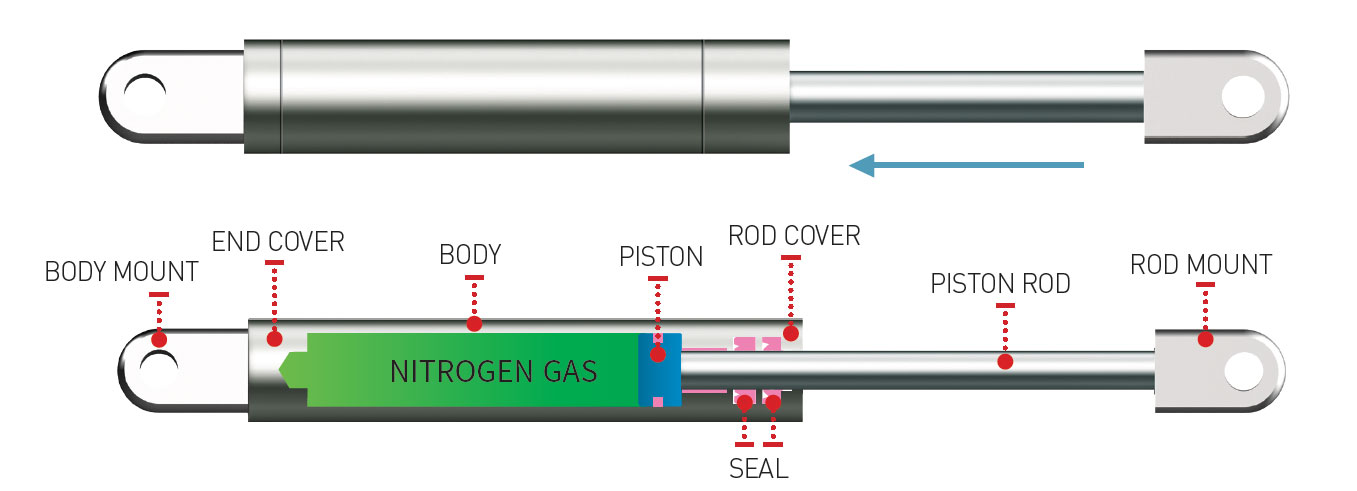
Gas Spring includes Cylinder, Piston Rod and End cover.
There is compressed Nitrogen Gas in the cylinder and It is possible to control the velocity in compression
and tension by operating check valve of Piston and orifice.
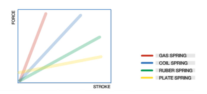
Gas Spring has various strengths, including small Spring Constant, Long Stroke,
Speed Control at compression and Stable Strength compared to general plate spring or coil spring
and is widely used across the industries.
Spring performance curve comparison
Install Method
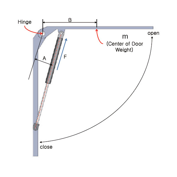
To get smooth operation of gas spring, please install it like above picture (Body of gas spring should be located upward)
- F: Spring Force(N)
- W: Door Weight(kg)
- A: Vertical distance from Hinge to Gas Spring(m)
- B: Distance from Hinge to the center of gravity(m)
- N: Number of Gas Spring
- G: Acceleration of gravity(9.8m/s2)
 Model selection
 Contact


